MTS-5100/MTS-5000 Software Version 2.06 Features
Learn about some of the significant new features in Software Version 2.06 for the MTS-5100 and MTS-5000 Protective Relay Testing Systems.
Table Of Contents
Productivity Mode Improvements
ANSI 87 Three-Phase Differential Mode: SEL-487E Relay
ANSI 87 Three-Phase Differential Mode: SEL Negative-Sequence Differential Relays
ANSI 51 Time Overcurrent Curves for Cooper Reclosers
Miscellaneous Productivity Mode Improvements
Harmonic Ramps
Pulse Counter (for testing watt-hour meters)
Graphical Display of Sequence Vectors
General Usability Improvements
Enhanced USB keyboard operation
Improved Key-Label Selection with Rotary Dial
Minor Features and Enhancements
In Conclusion
Productivity Mode Improvements
ANSI 87 Three-Phase Differential Mode: SEL-487E Relay
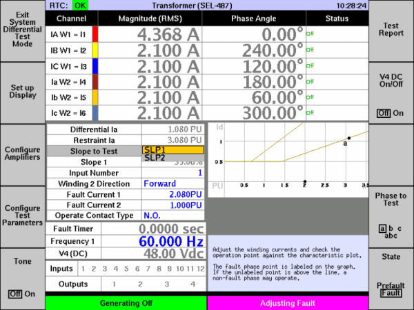
The SEL-487E transformer differential element is unusual, in that it uses more than just restraint current to select slope 1 or slope 2. Note in the image below that two traces are shown on the graph (one for each slope), and there’s a setting for “Slope to Test.” Most differential relays have a single trace, with each slope occurring only in a specific restraint current range, so that a particular restraint current always selects the same slope.
As stated in the SEL-487E manual:
Slope 1 is effective during normal operating conditions, and Slope 2 is effective when the fault detection logic detects an external fault condition.
In general the relay declares a fault to be external, and therefore enters high-security mode (longer operate time, slope 2 rather than slope 1) if it sees a change in restraint current not accompanied by a large enough change in differential current. It exits high security mode 60 cycles later, resetting that timer if there are additional step changes.
Testing slope 1 is the same as for most differential relays, except that you must apply pre-fault conditions for at least 60 cycles. For example:
- Set the “Slope to Test” setting to SLP 1, so that result values are calculated based on that slope.
- In Prefault (i.e., use F10 to select the “Prefault” state), set the winding current so that the restraint current is near the point on the curve you wish to test. The relay may enter high security mode when the currents step to the prefault values, but it will exit high security mode 60 cycles later.
- In Fault, start with both winding currents equal or nearly so (so that Ir/Id point is below the slope 1 line), then ramp one of the currents up or down from there. You can either configure an automatic ramp or increase the value using the rotary dial.
- Press PREFAULT and wait more than one second, so that the relay exits high security mode. When you press FAULT, the dot in the graph moves upward from the baseline. The relay should operate when the dot hits the slope 1 line.
To test slope 2, you need to make the relay stay in high-security mode. That means the test must finish quickly, which is best accomplished using an automatic ramp. For example:
- Set the “Slope to Test” setting to SLP 2, so that result values are calculated based on that slope.
- Set the number of fault states to 2, to define the currents in Fault 1 and Fault 2.
- Enable fault-state maximum durations, and set the duration for Fault 1 to 100ms.
- In Fault 1, set the winding currents so that the restraint current times √2 is higher than DIRTR and the differential current times √2 is less than DIOPR. The differential current must also be below the slope 2 line. When you apply those currents, the relay will enter high security mode, so it will not trip immediately even if the initial point is above the slope 1 line.
- In Fault 2, configure an automatic current magnitude ramp, so that the Id/Ir point starts below slope 2 (5% below, for example) and ramps to just above it (5% above). Set the ramp rate high enough that it finishes within 800ms, so that the relay will still be in high security mode when the ramp ends. The total time for Fault 1 and Fault 2 is at most 100ms + 800ms = 900ms, which for a 60Hz system is less than the relay’s 60-cycle timeout for high security mode.
- Press FAULT. Fault 1 currents will be generated for a short time, which should not cause the relay to operate. After that short time, the currents will ramp in Fault 2, and the relay should operate when the Id/Ir point passes the slope 2 line.
Apart from slope 1 / slope 2 selection, testing the SEL-487E is the same as for any other transformer differential relay.
ANSI 87 Three-Phase Differential Mode: SEL Negative-Sequence Differential Relays
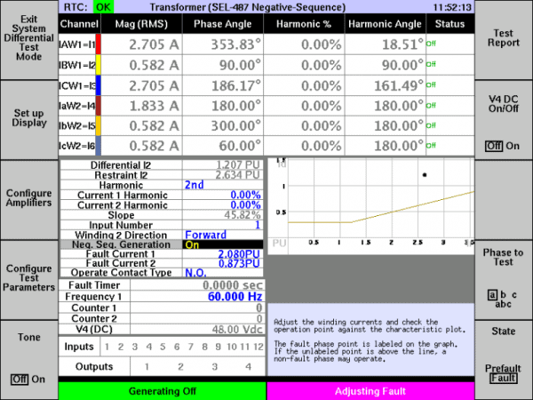
The SEL-487 relay has a unique “negative sequence differential” protection element. The three-phase differential productivity mode now includes support for this relay. Specifically:
- The differential and restraint current readouts, and the point on the characteristic graph, are calculated from the compensated negative sequence currents, as they are in the relay.
- The “Neg. Seq. Generation” setting lets you reverse the phase ordering, to produce test cases over a wider range of restraint currents.
Apart from those specifics, testing works as it would for any of the other supported relays. As with all supported relays, the configuration menu lets you configure the relay settings so you don’t have to calculate anything.
ANSI 51 Time Overcurrent Curves for Cooper Reclosers
- In Productivity Modes, when you select “51: Inverse Time Overcurrent Relay Test Mode,” the list of basic curve types now includes “Cooper Recloser Time Overcurrent Curve.” Selecting that option allows you to pick a specific curve type: Cooper A, B, C, E, K, N, R, W, 2, 3, 8, 8*, 8t, 9 or 11.
- Manta now offers a 14-pin recloser test cable compatible with several Cooper reclosers. Contact us for details.
Miscellaneous Productivity Mode Improvements
We have made several small improvements to productivity modes, including:
- In 50 and 51 (overcurrent) modes, you can now enable and adjust voltage channels. This feature is essential for testing directional relays.
- Productivity-mode timing settings and results can now be provided in cycles. In the “Advanced Settings” menu, a new setting “Time Unit for Auto Test Modes” lets you select “Seconds” or “Cycles.” The test screens and reports for automatic timing tests present the results in the selected unit.
- 50 mode (instantaneous overcurrent) now has a “Reset Time” setting for its automatic operate time test. This setting determines the inter-pulse pause time, typically so a 51 element can fully reset before each test shot.
Harmonic Ramps
Harmonic magnitudes and phase angles now use single-setting adjustment, except when the fault type is Arbitrary.
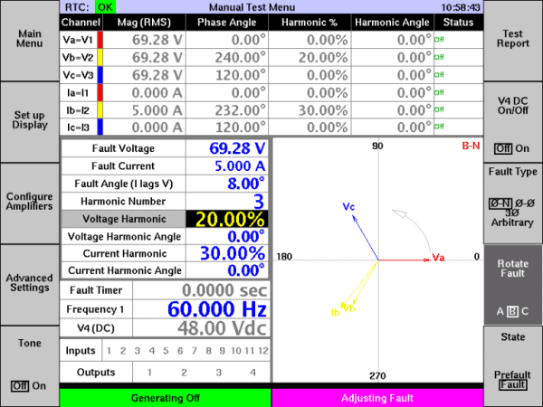
In the screen capture below, harmonics are enabled for a phase-to-neutral fault. Note that there is a single “Voltage Harmonic” setting and a single “Current Harmonic” setting (plus harmonic phase angle settings for each). The entered values are reflected in the upper grid for the fault phase (B, in this case), and they follow the fault rotation setting.
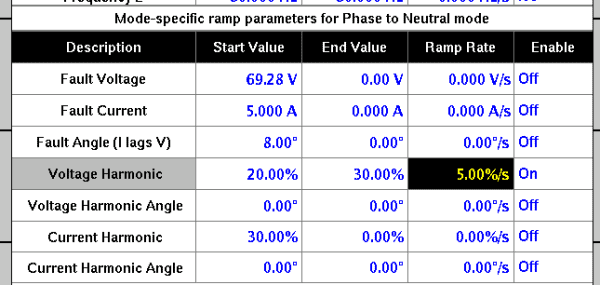
You can also ramp the harmonics (again for all fault types except Arbitrary). In the example above, pressing F4 (Advanced Settings) then F3 (Ramps) brings up the ramp settings, which now include harmonics. You can configure those to ramp harmonics at a precise rate from one level and/or angle to another. For example, below we have set the voltage harmonic to ramp from 20% to 30% at 5% per second.
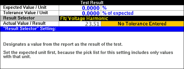
When saving an XML test report for use with RapidReporter™, you can include the as-ramped end harmonic values to document the test result. Using the example above, after pressing F6 “Test Report” then F10 “Save,” the available “Result Selector” values include “Flt/ Voltage Harmonic” (voltage harmonic magnitude in Fault), as shown below.
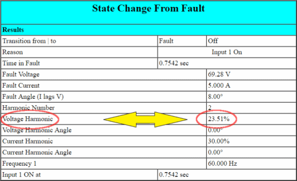
If you’re using HTML reports, you don’t need to do anything special to include harmonics. The per-fault-state HTML tables always include harmonic magnitudes and phase angles, if they are enabled when you run the test.
Pulse Counter (for testing watt-hour meters)
In previous versions of the software, from Manual Test you can press F4 (Advanced Settings) then F2 (Set up I/O and Timers) then F9 (Configure Timers) to define programmable timers. In Version 2.06 that key is now “Configure Timers and Counters.”
In the image below, two counters have been configured:
- Counter 1 causes a transition from Prefault to Fault when input 1 pulses twice.
- Counter 2 causes a transition from Fault to Postfault (or “Off”, if Postfault is disabled) when input 1 pulses a further ten times.
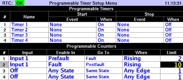
To run this test, set the “Go To” state for input 1 to “Same State” in “Fault State Control,” so that input 1 affects the fault state only when it pulses the given number of times. Also in “Advanced Settings,” make sure “Fault Incidence Angle (FIA)” is set to “Random”, because any other value affects timing.
This is a typical method for testing an energy (watt-hour) meter using the settings above:
- Set up conditions in Fault producing a known amount of power. Also configure Prefault to generate a similar amount of power, or perhaps a higher power level. In the “Display” menu, you can also add, if you like, a readout for the power level.
- Connect the pulse output of the meter under test to input 1 on the MTS-5100 or MTS-5000.
- Start generating in Prefault. On the second pulse, generation will switch from the Prefault state to Fault. The reason for using Prefault in this manner is to make sure that Fault starts immediately after one of the meter’s output pulses, so you’re counting an integer number of pulses. The reason for requiring two pulses in Prefault is that the meter may be mid-pulse at the start of the test, and the second pulse is therefore more accurate.
- Generation continues in Fault at your defined power level for the number of pulses you selected on counter 2. In our example that’s 10 pulses. If you use a power of ten, the calculation in the next step is really easy.
- On the last pulse, generation stops. The on-screen “Fault Timer” value reads out the time for the given number of pulses, accurate to within 0.1ms. Divide by the number of pulses and you have the time per pulse. Since you also know how much power you were generating, you now know the amount of energy per pulse, which you can compare against the specifications for the meter.
Graphical Display of Sequence Vectors
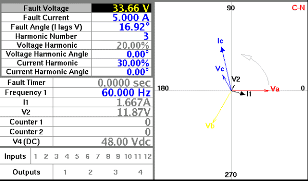
The main test screen for Manual Test and some of the productivity modes has always displayed the per-channel voltage and current vectors in graphical form. Version 2.06 adds the ability to superimpose vectors corresponding to the symmetrical components of the three-phase sets (positive-sequence, negative-sequence and zero-sequence voltages and currents).
Settings for the feature are in the Display Setup Menu (from Manual Test, press F2). When the feature is enabled, the vector diagram includes whichever sequence quantities you have selected to be shown in the dynamic display area on the test screen.
In the screen capture below:
- The new “Show Sequence Vectors” setting is set to “On,” to enable the feature.
- Row 3 and Row 4 have been configured to show positive-sequence current (I1) and negative-sequence voltage (V2), respectively.
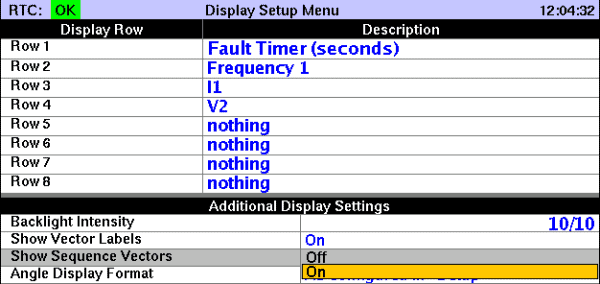
Back in the test screen, in addition to the per-phase voltages and currents, the phasor diagram now has additional arrows for I1 and V2. Note that it is not necessary to enable display of both the magnitude and angle for a sequence quantity in order to display its vector. Simply enable the magnitude readout.
General Usability Improvements
Enhanced USB keyboard operation
You can now filter long drop-down lists by entering the first few characters on a keyboard. As you type characters, only the choices matching those characters will be displayed. For example, in the Display Setup Menu, by typing an an “i” only entries beginning with that character are displayed. Typing additional characters further reduces the list of choices to just entries beginning with those two or more characters.

Also a change has been made to some of the shortcut key definitions. In Version 2.05, press the P, F, R and H keys on a USB keyboard to emulate pressing of the PREFAULT, FAULT, RESET and HELP keys on the front panel. In version 2.06, press Ctrl-P, Ctrl-F, Ctrl-R, Ctrl-H instead (i.e. hold down the Ctrl key and press the letter). Those key combinations are more difficult to press by mistake.
Improved Key-Label Selection with Rotary Dial
In several places, the software defines a function key so that pressing the key advances to the next in a series of selections. For example, in Manual Test, the F8 key is used to select the fault type, and pressing it advances to the next fault type.
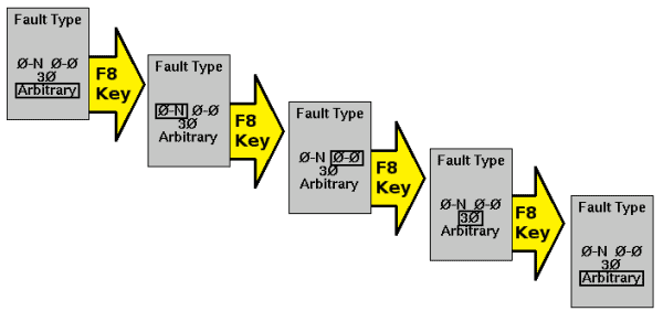
When there are only a few different values for the key, that’s an easy and reliable selection. Sometimes, however, there are many values available on a function key. For example, the F10 key in Manual Test lets you select the fault state to edit. Usually those states include only Prefault, Fault and perhaps Postfault. When performing an Arbitrary test with all possible states enabled, however, there are 27 different values:

If you make a selection one time too many, you need press many times to get back where you started.
In Version 2.06, you can still select values that way, but there is a new method:
- Press and hold the function key.
- While still holding the function key down, select a value using the rotary dial. If you rotate too far, simply rotate back the other way.
- When the value you want is showing, release the function key to select it.
To help users discover this feature, a message appears if you press this type of function several times:

Minor Features and Enhancements
Minor features and enhancements include:
- The calculated display selections now include per-unit V/Hz, (relative to the nominal voltage and system frequency).
- MTS-5100 slave configuration (6-voltage vs. 3-voltage/3-current) is now saved for every run.
- Selectable default input type (wet vs. dry) can be saved for every run.
- When generation is stopped due to a monitored condition (shorted output, for example), a button now allows a user to save the record and send it to Manta for technical support.
- The installer for MTS-5×00 Remote Console allows the user to select where to place the shortcut(s) and data folder.
- Reports now include custom-defined timer names.
- Arrow keys can now be used to select characters for text entry (until now you had to use the rotary dial).
In Conclusion
That was just a brief introduction to the new features in Version 2.06 of the MTS-5100 / MTS-5000 software. We are preparing training material which will dive deeper into some of the individual features. If you need assistance you can contact Doble.
You can download the latest MTS-5000 / MTS-5100 software and related PC software from our customer area, under MTS-5000/MTS-5100 Software.
