What are “Productivity Modes” in the MTS-5100?
Short Answer
A “Productivity Mode” is a helper mode in the MTS-5100 Protective Relay Testing System for testing a specific kind of relay, protection element or piece of substation equipment. For example, the ANSI 51 Time Overcurrent Relay Test Mode is optimized for testing time-overcurrent relays or the time-overcurrent elements in multi-function digital relays.
Productivity modes include both manual and automatic test facilities. In general, “helper” functionality assists you with manual testing. For example, in most of the differential relay test modes, the characteristic graph for the relay is shown, and you can see the point represented by your differential and restraint current on a graph. That way you can tell visually whether the relay operates where it should. An example of an automatic test facility would be an operate-time test for a 51 time-overcurrent relay, in which the test set automatically applies current at various multiples of the pickup level, comparing the relay’s operate time with its characteristic curve and tabulating the results in a test report.
Test reports may be generated for both manual and automatic tests. You can also use ramping and other features to automate tests your way, using the “manual” facilities in each productivity mode.
Longer Answer
When you turn on an MTS-5100 Protective Relay Testing System, the first menu you see has these key labels in the upper-left corner. Those three keys are the most common ones you’ll use from the main menu.
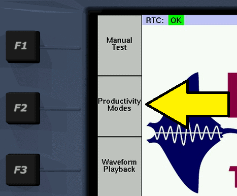
- F1 Manual Test lets you configure test cases when you know what currents, voltages and phase angles you need. It has helper sub-modes for different fault types (phase-to-neutral, phase-to-phase, etc.), but nothing that’s specific to a particular relay or protection element.
- F3 Waveform Playback plays back COMTRADE waveform files, recording input events in the process.
- F2 Productivity Modes, though, is what this article’s about.
When you press F2 Productivity Modes, you’re presented with a top-level list of the available modes:
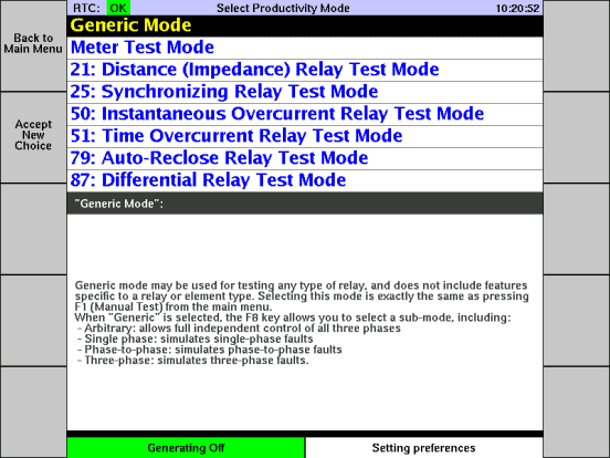
“Generic Mode” is the same as F1 Manual Test from the main menu. Some people like to be able to see all the top-level modes in one list, so we’ve included it here. The other modes are for the most part optimized for testing a particular type of relay or a particular protection element. That just leaves “Meter Test Mode”, which is optimized for testing panel meters and the metering capabilities of digital relays.
Perhaps the best way to give you a feel for what productivity modes are all about is with an example.
Example: “21: Distance (Impedance) Relay Test Mode”
As an example of a typical productivity mode, let’s look at the first of the relay-specific modes on the list, which is ANSI 21: Distance (Impedance) Relay Test Mode. You’d use this mode to test a distance relay, such as the ABB KD series, or the distance element in a digital relay like the SEL 321 or GE D60.
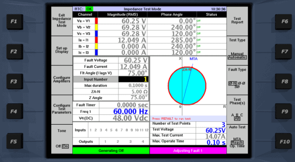
This mode illustrates characteristics that are common to most of the relay-specific test modes:
- Instead of a vector diagram, the graphic in the lower-right corner is something appropriate to the protection element being tested. In this case it’s an impedance diagram. In some modes, the type of graphical visualization changes depending on which specific type of test you’ve selected.
- The F4 key is “Configure Test Parameters”. That key brings up a menu to enter relay settings and other test parameters.
- Some of the test settings also appear under the impedance diagram, so you can adjust them without going into the “Configure Test Parameters” menu. The list of settings changes depending on which test you’ve selected.
- The F7 key lets you select between “Manual” and “Automatic” sub-modes:
- “Manual” means that you can adjust currents and voltages in the various fault states, and cycle through those fault states. You’re in total control of the testing methodology. The test set calculates the impedance for the selected test phase, and plots it on the diagram, to help you quickly determine whether the relay is working correctly.
- “Automatic” (shown in the image above) presents a selection of automatic tests on the F10 key. In this case, there are automatic tests for MTA (test the relay’s accuracy in assessing impedance angle), Reach (test the accuracy of several points along the top edge of the characteristic) and Op. Time (test the operating time at various points within the impedance characteristic). For each of those tests, you set up some parameters, press Prefault, and the test set does the rest.
- After each test, whether it’s manual or automatic, you can obtain a test report using the F6 key.
Example: Manual Reach Test in ANSI 21 Mode
When F7 is set to “Manual”, 21 mode looks like this:
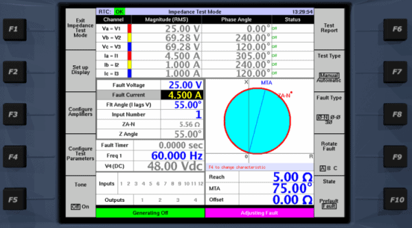
In this case I have entered 1A prefault current, and a 4.5 amp phase-A fault, with voltage dropping to 25V. In the impedance diagram, notice that the dot for ZA-N is outside the characteristic MHO circle. The test set calculates the impedance (ZA-N, Z Angle) for you, taking the zero-sequence K-factor into account if it’s a phase-to-neutral (“ground distance”) fault. You don’t have to do any calculations at all. In this example, I have left the K factor at zero, just for simplicity.
To test a relay, wire the relay’s CT and PT inputs to the V1,2,3 and I1,2,3 terminals on the test set, and wire the relay’s contact output to the test set’s Input 1 terminals.
Let’s say you want to do a manual reach test at 55°. Press Fault to start generating, then increase the current slowly until the relay operates, using the rotary dial on the front panel of the test set. If you want a level of automation in your test, you can configure the current to ramp upward automatically when you press Fault. That’s a topic for another article, but if you’re curious I have prepared a YouTube video showing how to configure automatic ramping (click for video).
As the current increases, you’ll see the ZA-N dot move toward the origin, always at a 55° angle. At some point, the relay operates.
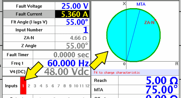
When the relay operates, the Input 1 status turns red to indicate “closed”, and the MHO circle in the diagram turns green to indicate “operated”. With the default settings, the test stops at that point, because Input 1 is configured to transition out of the Fault state.
The impedance values on the screen are captured and frozen when the relay operates. You can see that the relay operated at a reach of 4.66 Ω at 55°. If you’re recording your results on a test sheet by hand, you can write in those numbers.
You can also generate reports in electronic form. When the test finishes, you can press F6 to see a test report. Just like the test screen, the report below indicates that the relay operated at a reach of 4.66 Ω at 55°.
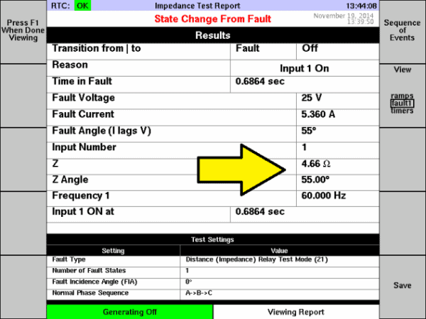
You can do several things with that report, including:
- View it using a web browser on your PC, using the web server that’s built into the MTS-5100 test set. You can cut and paste the HTML report into a word processor or spreadsheet if you like, to prepare a report in a format of your choosing.
- Save that same HTML report to the test set’s internal flash memory, or to a USB flash storage device plugged into the test set.
- Save the report in an XML format that’s recognized by Manta’s free RapidReporter® program, which organizes your test reports in a database and lets you print them. RapidReporter® also lets you export the reports back to the test set, which is able to re-run each test using the settings that are contained in the XML report file.
In any of those cases you can define an expected value and a tolerance limit, so the report has a PASS or FAIL result. You can also add fields to the test report identifying the location, equipment being tested, etc., which is particularly helpful in meeting NERC reporting requirements.
The productivity mode, even when set to “manual”, makes it easy to test this specific relay, as compared with using the Manual Test mode. To be even more productive, the main thing you’ll need to do is save and organize your test plans, so that you don’t have to re-enter the settings each time. You can save a setting file in Manual Test or in any of the productivity modes. When you load the file, everything’s all set up just as it was before you saved. You can keep a sequence of test setting files in a directory on the test set’s internal flash drive or on a USB flash storage device.
That way, when you’re at the substation performing the tests, you can just do a repeated series of:
- Load the next test settings file in the sequence
- Run the test
- Save a report
For the ANSI 21 reach test, testing each of the phases in your ground distance relay, you might need something like 9 setting files (3 phases, 3 test angles per phase). Loading 9 setting files in succession, running the tests and saving the reports, is a quick operation, but to be even quicker you can use the “Automatic” sub-mode.
Example: Automatic MTA Test in ANSI 21 Mode
For an example of an automatic productivity-mode test, let’s test the Maximum Torque Angle (MTA) on a distance relay.
To begin, we’ll press F7 until it says “Automatic”, and F10 until it says “MTA”. There are also automatic reach and operate-time tests, but for our example we’ll do an MTA test.Below the impedance diagram there are settings specific to the MTA test:
- Test voltage and current, which define the impedance magnitude during the test
- Start angles for a left and right ramp-in, so you can make sure the test starts outside the characteristic. You might need to adjust this value if the relay is set with a large zero-sequence K-factor, because that changes the relationship between current angle and impedance angle.
The F9 key sets Test Phase(s) to “all”, which means it will test the A, B and C phases in sequence.
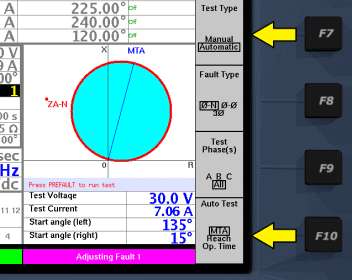
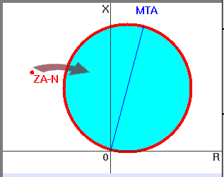
If we just leave those at their default values, then press Prefault, the phase A impedance will move smoothly along a curve toward the MTA line as shown above. The current phase angle starts at the specified “Start angle (left)” and decreases until the relay operates. The area below the diagram changes to a text readout, letting you know what’s happening as the test progresses. When the test is complete, it reads out a summary of the results.

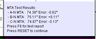
As the screen says, you can press F6 to see a test report:
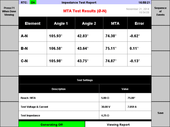
Note that the table of results shows you the results for all three phases, and you can see at a glance the MTA error on each phase. As always, you can press F10 to save the report, and you can also view it with a web browser to copy and paste into a word processor or spreadsheet.
A Brief Look at a Few Other Productivity Modes
Other productivity modes work very much like the ANSI 21 Distance (Impedance) Relay Test Mode. I won’t go into detail describing those other modes, but here’s a quick rundown of a few popular ones.
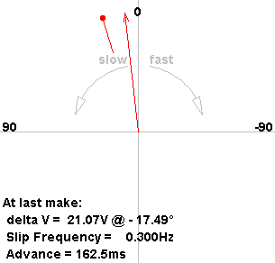
The ANSI 25 Synchronizing Relay Test Mode lets you test synchronizing or synchrocheck relays (GE GXS, Basler BE1-25, etc.).
The visualization graphic is a synchroscope. The on-screen readout tells you the slip frequency and advance when the relay operates. The point of operation is shown as a line with a circle on the end. The mode also accounts for breaker operation time, which you can see in this diagram as a difference between the captured vector and the operate line.
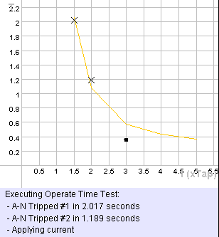
The ANSI 51 Time Overcurrent Relay Test Mode has automatic tests for the pickup level and operate time of a 51 element or relay. You can pick the type of relay or curve you’re testing, and the test set calculates everything for you (with the option to override those calculations, of course).The operate-time test, for example, plots the relay’s defined curve with time as the Y axis and multiple of pickup as the X axis. As it injects current at several pickup multiples, it shows a rising dot indicating how long current has been applied. When the relay operates, an X is drawn on the graph so you can see right away whether the relay is following the right curve.
The test report shows the amount of error at each point, on each test phase.
Meter Test Mode
Meter test mode is unlike the other modes, in that it does not test the operation of protective relays. It’s optimized for testing meters, and also for testing the metering capabilities of digital relays. It can also be used for testing transducers, connecting the transducer output to the 10V or 20mA input on the test set.
Key Concepts
In summary:
- Productivity modes make it quick and easy to test specific kinds of relays and protection elements
- Productivity modes include both manual and automatic tests
- Test reports can be saved on the test set, a USB flash memory device or a connected PC, and they work with Manta’s free RapidReporter® program
- To be really efficient, you should save your test plans as setting files, so you can load each one and run it without re-entering any settings
- Meter Test Mode is, at time of writing, the only productivity mode that tests something other than a relay or protection element
