How to test IEC 61850 / GOOSE using the MTS-5100
Modern electric power utilities have been increasing their standardization on IEC 61850 communications within substations in recent years. It is becoming common for substations to use IEC 61850 GOOSE (Generic Object Oriented Substation Events) as a replacement for individually-wired signals between protective relays and other equipment. GOOSE messages allow low-latency, real-time transmission of events over an Ethernet network (copper or fiber) which would previously have required a large number of individual signal wires. Each network message encodes a potentially large number of signals such as protection element operate indications, breaker status and blocking signals.
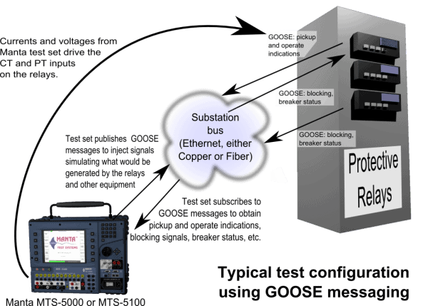
To meet the challenge of testing those systems, the software for the Manta MTS-5000 and MTS-5100 Protective Relay Testing Systems includes IEC 61850 GOOSE messaging capabilities. As is always the case with Manta test equipment, we have made simplicity and ease-of-use our top priorities. GOOSE messaging integrates seamlessly with the other features of the test-set software, so apart from some initial set-up, testing using GOOSE messages is the same as traditional testing using relay inputs and output contacts.
This article explains how to use Manta relay testing systems to test substations and equipment with IEC 61850 GOOSE messaging. When it was written, the latest released MTS-5×00 software version was 2.04, so the description herein relates to that software version.
Capabilities
There are two basic aspects to the IEC 61850 GOOSE messaging software feature:
- Subscribing to receive GOOSE messages, and using the point values in those messages as though they were physical status inputs. The messages would normally originate in relays and other equipment on the substation network.
- Publishing GOOSE messages that mimic those which would be sent by substation equipment that has been disconnected, to inject point values that simulate substation events.
Message layouts can be programmed using three methods:
- Listening to Ethernet traffic, to discover messages that are being sent by relays and other equipment. This is often the most convenient way to configure tests in which the test set has to subscribe to incoming GOOSE messages.
- Loading a standard SCL / ICD file (“Substation Configuration Language” / “IED Capability Description”), containing GOOSE definitions. The format of those files is specified by IEC 61850-7-X standard documents, and they’re generated by a lot of relay configuration utilities, such as SEL acSELerator Architect®. If your substation uses GOOSE messaging, you may already have the required files.
- Loading a previously-saved file. Once you have the GOOSE configuration the way you want it, you can save the entire configuration to a setting file, and restore that file for a subsequent testing session. As with any type of setting file, those can also be moved from one test set to another.
As of Version 2.04, the MTS-5×00 software supports only binary (SPS, DPS) point types. It does not, for example, use the analog points found in some GOOSE messages. If you require improvements to this feature, please contact support with your request.
GOOSE input points may be used in Manual Test or any of the Productivity Modes. They also appear in the waveform display and sequence of events for the Waveform Playback feature.
GOOSE output points may be defined in Manual Test or a Productivity Mode to assert and deassert based on the same “function” settings used for contact outputs:
- “Off” or “On.”
- 51A/B breaker feedback.
- Permissive / Unblock.
- On during a selected fault state or a custom set of fault states.
- Mimicking an input.
As of software version 2.04, GOOSE outputs are not supported in Waveform Playback.
Example, Using Two Test Sets
This section will provide an example illustrate how the feature works.
We’ll use one test set (an MTS-5000) as the publisher, and one (an MTS-5100) as the subscriber. Screen captures are used to show what is happening on each test set. Both test sets were running Version 2.04.
Preparing Each Test Set
To use the IEC 61850 / GOOSE feature, you need to enable real-time networking. It is disabled by default, as of Version 2.04, because on rare occasions it prevents the FTP and HTTP servers from working with certain network configurations. It’s easy to disable later, if there’s a problem, so enabling it is risk-free.
From the main menu on each test set (MTS-5000 shown here), press F10 “Setup”…
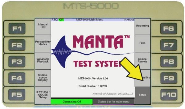
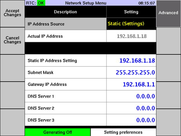
then F5 “Set up Network”,…
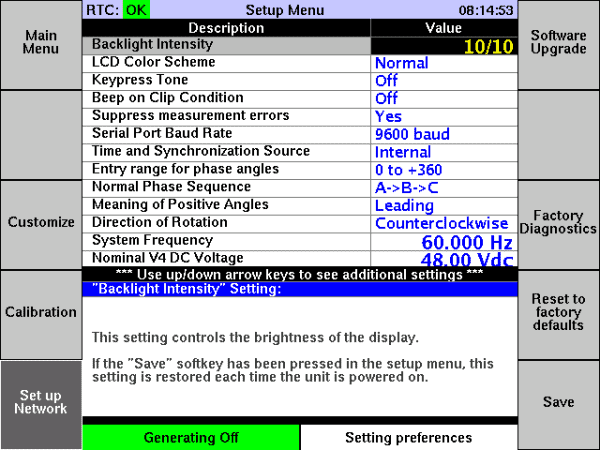
then F6 “Advanced.”
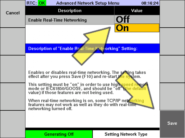
If the “Enable Real-Time Networking” setting is set to “Off,” change it to “On” and press F10 “Save.” When the message appears asking you to do so, cycle power to the test set. If the setting already “On,” you can just press F1 a few times to get back to the main menu.
Now Real-Time Networking is enabled, and you’re ready to use IEC 61850 GOOSE messaging. Repeat the process for the other test set.
Publishing a GOOSE from the MTS-5000
To get to the IEC 61850 menu, press the F5 key from the main menu:
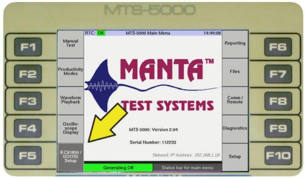
That key is programmable, and if it’s programmed for some other function you can also get to the menu by pressing F8 (Comm / Remote) then F5.
If you get a message saying that you need to enable real-time networking, please see the instructions in “Preparing Each Test Set”, above.
When you first go to the IEC 61850 menu, this is what you see:
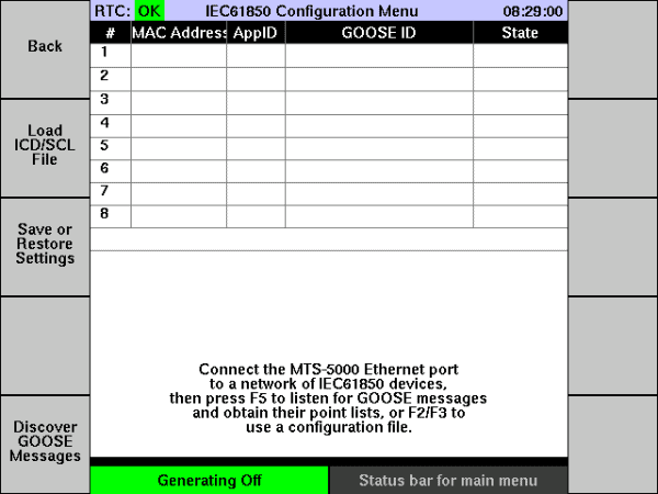
There’s a grid in the middle showing all the known GOOSE messages. So far, there are none. The keys down the left side let you load that grid using one of three methods:
- Load an ICD/SCL File, which would have been produced for configuring the relays and other equipment at the substation. This file can often also be obtained using the relay vendor’s relay configuration software to extract the definitions from a relay. This is the method we’ll use in our example.
- Restoring a file that you previously saved.
- Listening on the Ethernet connection and recording whatever GOOSE messages arrive.
To load an ICD/SCL file, press F2. For this example, a file was placed on the test set using FTP, but you can also use a USB storage device and either copy the file to the test set’s internal flash memory (using the “Files” menu) or load it directly from the USB device.
Select a file from the list using the up and down cursor arrow keys, then press the F5 key to load it.
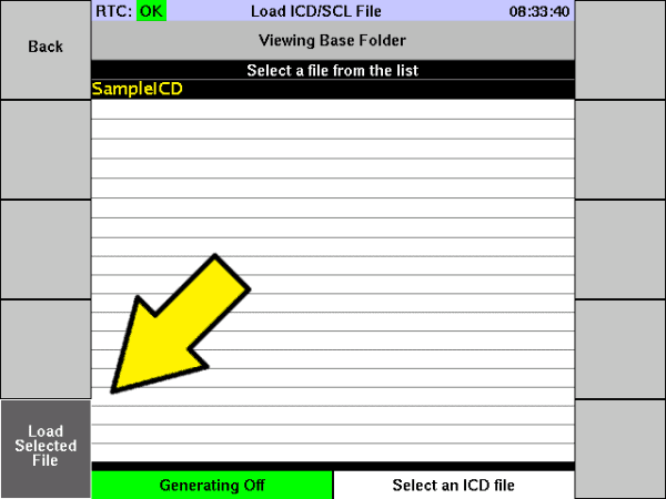
Some GOOSE message definitions appear at the top of the screen.
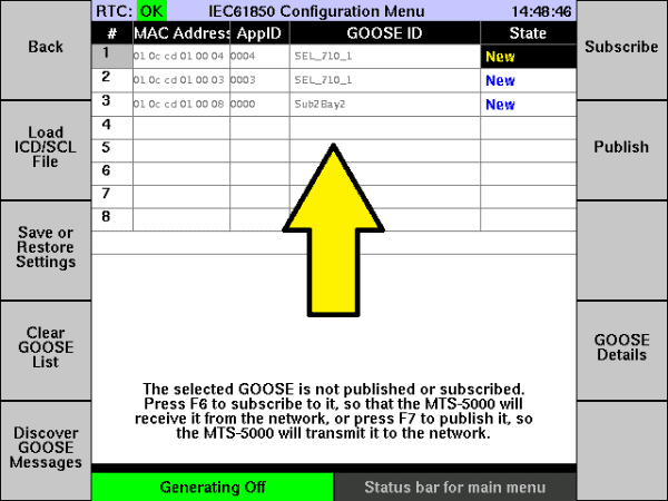
In this case there are three GOOSE messages defined in the ICD file: SEL_710_1 appid 4, SEL_710_1 appid 3 and Sub2Bay2 appid 0.
You can look at the details of each GOOSE by pressing F9 “GOOSE Details.” For example, here are the details for Sub2Bay2:
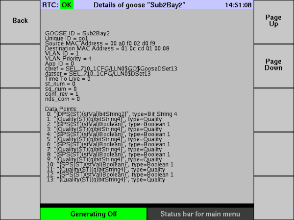
Press F1 to return to the IEC 61850 menu. To publish a GOOSE message, select it in the list using the up/down cursor arrow keys, then press F7 “Publish.”
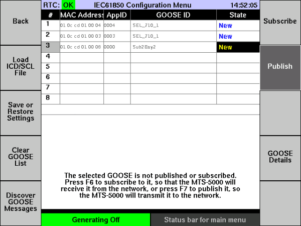
The state for that GOOSE changes to “Published,” and the F7 key label changes to “Unpublish” when that GOOSE is selected.

The MTS-5000 is now sending the Sub2Bay2 GOOSE out at regular intervals, and it will also be sent whenever any of its point values change (once we’ve assigned those, as described later).
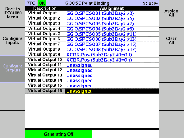
The on-screen help says that the next thing to do is to press F8 “Configure GOOSE Points.” Doing so presents a list of “virtual output” points, and we need to assign those to the points in the GOOSE message.
You can use the cursor arrow keys to select a “Virtual Output” row, and turn the rotary dial to select a GOOSE output point for each one. If you’re only publishing a GOOSE with a small number of output points, though, the easy approach is to press F6 “Assign All”. Each virtual output is mapped to one of the binary points in the GOOSE message.
Subscribing on the MTS-5100
On the MTS-5100, we’ll go to the IEC 61850 menu the same way we did for the MTS-5000: either by pressing F5 from the main menu, or if it has been programmed for another function, by pressing F8 “Comm/Remote” then F5. Apart from appearing on a larger screen, this menu looks the same on the MTS-5100 and the MTS-5000.
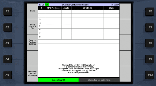
To define the GOOSE messages we want to receive, we could load an ICD/SCL file or restore a previously-saved setting file. For the purpose of this example, though, we’ll use F5 “Discover GOOSE Messages.”
With the publishing MTS-5000 (configured as described above) and the recieiving MTS-5100 on the same network, pressing F5 starts the discovery process. A progress bar times out after about one minute of discovery (because GOOSE sources normally arrive at least once per minute).
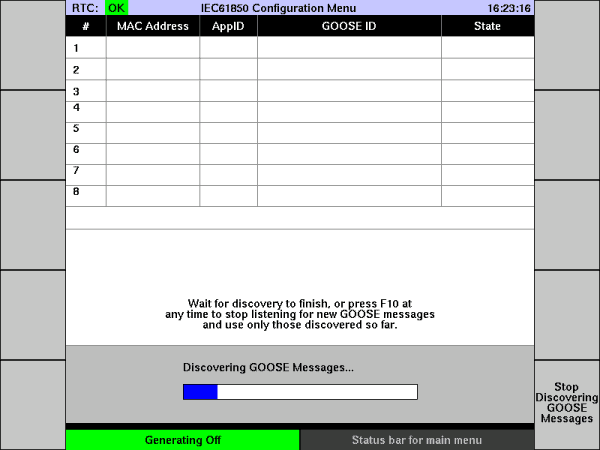
As GOOSE messages are received, they appear in the upper grid. In this case, we’re connected to the MTS-5000 that is sending the Sub2Bay2 GOOSE, so that’s what appears.
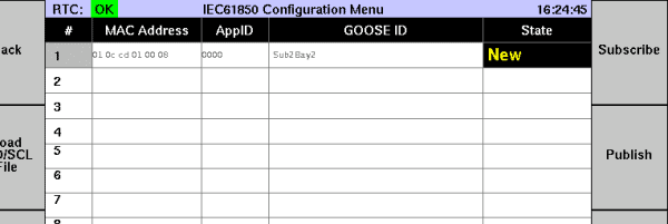
To subscribe to the GOOSE, select it (although in this case there’s only one, so it’s already selected), and press F6 “Subscribe.” The status changes to “Subscribed,” and the help text at the bottom explains what to do next.
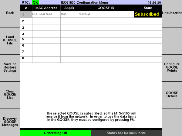
Per the instructions on the screen, the next thing to do is press F8 “Configure GOOSE Points,” which brings up a list of “Virtual Input” points.
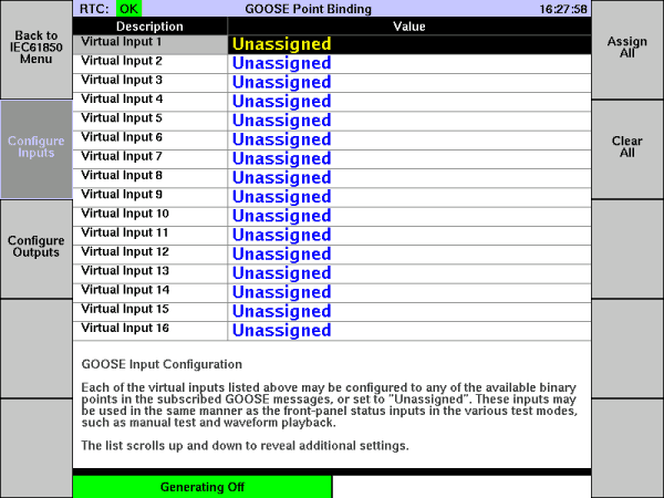
The easy way to assign the points, if there aren’t too many, is to just press F6 “Assign All.” That sets each virtual input to the next binary point in the message.
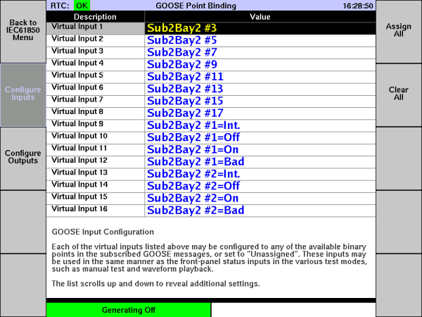
Those binary points are either single-point status (SPS) or double-point status (DPS). Each DPS point appears as four virtual inputs, each corresponding to a possible state of the DPS. For example, if the DPS point is for a breaker status, “Off” and “On” correspond to breaker open and closed, and “Int” corresponds to the intermediate state between those two. “Bad” indicates that the relay or other device has detected a problem with the input, such as both contacts closed when they should be break-before-make.
Running a Test
For this example, we’re making the MTS-5000 act like a relay, and using the MTS-5100 to test that pseudo-relay. Just to keep things really simple, we’ll use the Fault button in both cases, so:
- We’ll press Fault on the MTS-5100 to start the test shot, then;
- We’ll press Fault on the MTS-5000 to simulate a protection element operating in the relay under test, then;
- The MTS-5100 will detect that Fault has been pressed on the MTS-5000 and, treating it as an “operate” event, end the test shot.
On the MTS-5000, we need one of our GOOSE points to change state depending on the fault state it’s generating. Let’s use the “Sub2Bay2 #11” point, which as shown earlier is mapped to virtual output 5.
Pressing F1 a few times gets you to Manual Test, and from there you press F5 “Advanced Settings”, then F2 “Set up I/O and Timers.” In that menu, press F8 “Configure Outputs.”
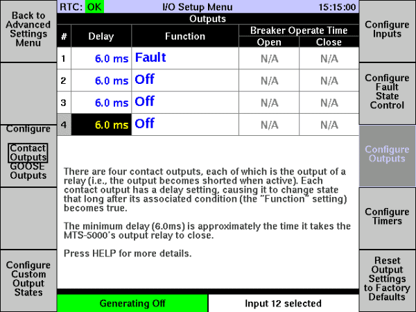
Note that the F3 key label (“Configure”) lets you pick Contact Outputs (the four outputs on the test set’s front panel) or “GOOSE Outputs” (the virtual outputs we defined in the IEC 61850 menu). Pressing it shows the GOOSE outputs.
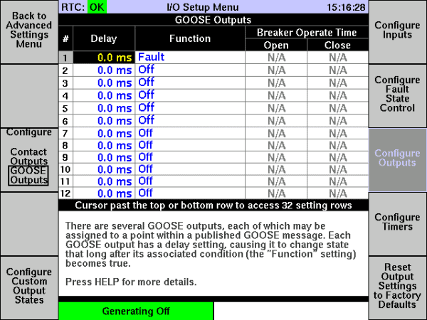
We want to set virtual output 5 so it turns on when we go into fault (i.e. when we press the Fault button). Select the ”Function” setting for input 5, and turn the rotary dial to select “Fault.”
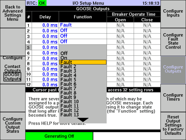
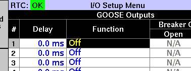
Also change GOOSE output 1 to “Off,” because in Version 2.04 you can’t have two GOOSE output points driven by the same fault state. When we release MTS-5×00 Software Version 2.05, that restriction will be removed.
Now we can press F1 twice to return to the Manual Test menu, and each time we go into Fault, virtual output 5 will turn on. The Manual Test screen shows the virtual output states at the bottom, so you can see when virtual output 5 turns on.
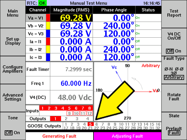
Now we have the MTS-5000 producing an indication on “Sub2Bay2 #11” when it is generating Fault. We need to make the MTS-5100 process that indication. In Manual Test / “Advanced Settings” / “Set up I/O and Timers,” we press F7 “Configure Fault State Control.” As was the case for outputs, the F3 “Configure” button lets us switch to GOOSE inputs.
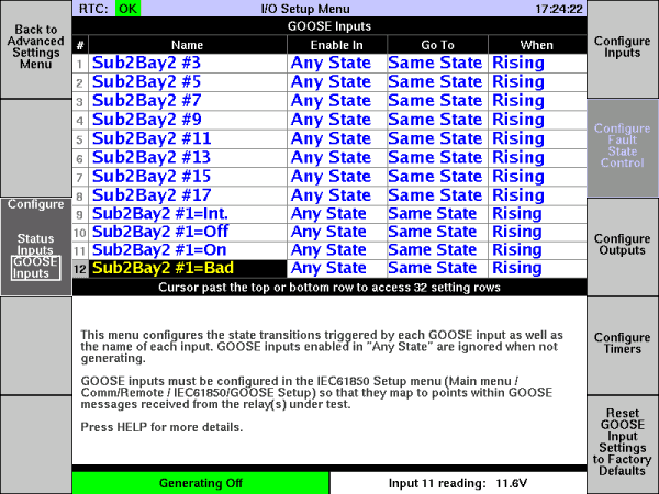
We’ll move the cursor to input 5 “Sub2Bay2 #11”, then set “Enable In” to “Fault” and “Go To” to “Postfault,” using the rotary dial.
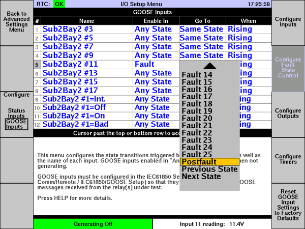
Now virtual input 5 will make the MTS-5100 go from Fault to Postfault. We’re not enabling the Postfault state, though, so it will go from Fault to Off. Pressing F1 twice returns you to the Manual Test screen.
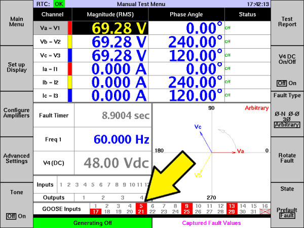
We’ll start the test shot by making sure both test sets say “Generating Off” in the lower-left corner, pressing Reset if necessary. Then we start the test shot by pressing Fault on the MTS-5100. Notice that GOOSE input 5 is not shown in red, because it’s not indicating “on.”
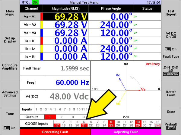
Remember that our MTS-5000 is simulating a relay, and that we’re using its Fault state to simulate a relay operation. Pressing Fault on the MTS-5000 causes it to assert GOOSE output 5. On the MTS-5100, we see that GOOSE input 5 asserts, and the test shot ends.
Pressing F6 shows us a test report. Pressing F7 a few times shows us the “fault1” report.
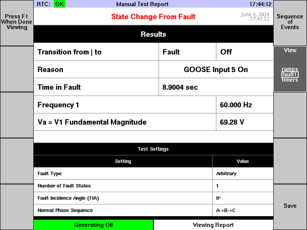
You can see that the transition from “Fault” to “Off” was caused by “GOOSE Input 5 On,” and that the time spent in fault was 8.9004 seconds (I was cutting and pasting screen captures during that time, so it took a while).
We have simulated what would happen with a real GOOSE-generating relay under test:
- Test set goes into Fault, generating currents and voltages which would make the relay operate.
- Relay element operates, causing a GOOSE point to change from “Off” to “On”.
- Relay sends a GOOSE message over the network, containing that new point value.
- Test set receives the GOOSE message, extracts the value, and registers the operation of the relay’s protection element.
- Test set ends the test shot.
